Fan-coil unit is the end device of air conditioning system. It is mainly composed of fan and coil unit, which provides direct air supply to the room to meet the requirements of cooling, dehumidification and heating, etc. The air supply volume of fan-coil unit is below 2380m /h, and the outlet static pressure is no more than 50Pa.As the end equipment of central air conditioning, the quality of fAN-coil determines the effect of indoor air conditioning.
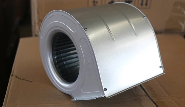
The fan adopts the design of the extended tuyere, and the upper mouth of the tuyere is provided with the rectifying pressure slot, which avoids the generation of eddy current noise in the tuyere air, as well as the complexity of the unit structure and the increase of material cost caused by the design of the tuyere guide plate.
The volute coil plate is equipped with reinforcing bars to avoid the noise generated during the fan operation.
| Model Performance | FP-34 | FP-51 | FP-68 | FP-85 | FP-102 | FP-136 | FP-170 | FP-204 | FP-238 | ||
| Rated Air Volume (m3/h) | Hight | 340 | 510 | 680 | 850 | 1020 | 1360 | 1700 | 2040 | 2380 | |
| Midle | 255 | 383 | 510 | 638 | 765 | 1020 | 1275 | 1530 | 1785 | ||
| LOW | 170 | 255 | 340 | 425 | 510 | 680 | 850 | 1020 | 1190 | ||
| Cooling Capacity(W) | Hight | 1800 | 2700 | 3600 | 4500 | 5400 | 7200 | 9000 | 10800 | 12600 | |
| Midle | 1440 | 2160 | 2880 | 3600 | 4320 | 5760 | 7200 | 8640 | 10080 | ||
| LOW | 1170 | 1755 | 2340 | 2925 | 3510 | 4680 | 5850 | 7020 | 8190 | ||
| Heating Capacity(W) | Hight | 2700 | 4050 | 5400 | 6750 | 8100 | 10800 | 13500 | 16200 | 18900 | |
| Midle | 2160 | 3240 | 4320 | 5400 | 6480 | 8640 | 10800 | 12960 | 15120 | ||
| LOW | 1755 | 2633 | 3510 | 4388 | 5265 | 7020 | 8775 | 10530 | 12285 | ||
| Input Power (W) | 12Pa | 37 | 52 | 62 | 76 | 96 | 134 | 152 | 189 | 228 | |
| 30Pa | 44 | 59 | 72 | 87 | 108 | 156 | 174 | 212 | 253 | ||
| 50Pa | 49 | 66 | 84 | 100 | 118 | 174 | 210 | 250 | 300 | ||
| Nominal power (W) | 12Pa | 8 | 10 | 16 | 25 | 40 | 40+12 | 25×2 | 40×2 | 40×2+16 | |
| 30Pa | 12 | 16 | 20 | 35 | 50 | 50+16 | 35×2 | 50×2 | 50×2+16 | ||
| 50Pa | 16 | 20 | 25 | 50 | 65 | 65+16 | 50×2 | 65×2 | 65×2+16 | ||
| Noise dB(A) | 12Pa | 37 | 39 | 41 | 43 | 45 | 46 | 48 | 50 | 52 | |
| 30Pa | 40 | 42 | 44 | 46 | 47 | 48 | 50 | 52 | 54 | ||
| 50Pa | 42 | 44 | 46 | 47 | 49 | 50 | 52 | 54 | 56 | ||
| Fan | Type | Forward multi - wing centrifugal double - suction fan | |||||||||
| Number | 1 | 2 | 2 | 2 | 2 | 3 | 4 | 4 | 4 | ||
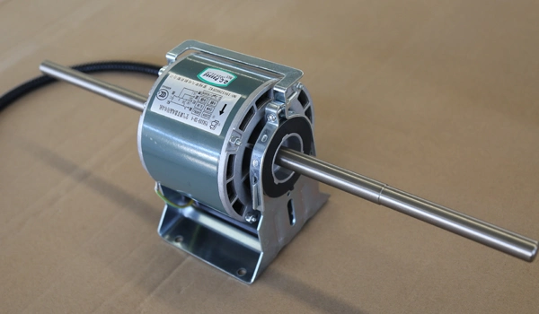
| Motor | Type | Capacitor run asynchronous motor (220V /50Hz, protection class IP20, insulation class E) | |||||||||
| Number | 1 | 1 | 1 | 1 | 1 | 2 | 2 | 2 | 2 | ||
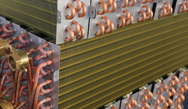
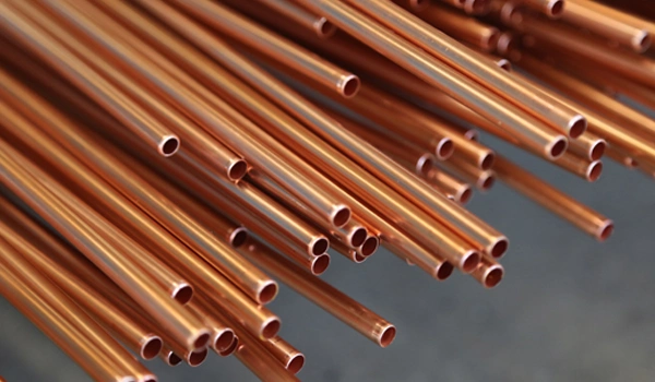
| Heating Exchanger | Structure | Copper tube series aluminum sheet , mechanical expansion | |||||||||
| Pipe size | Rc3/4(Taper pipe thread) | ||||||||||
| Other Item | The design pressure is 1.6mpa and the test pressure is 2.5mpa | ||||||||||
| Weight(kg) | WA Without Air Retuming Box | 14 | 15 | 17 | 19 | 20 | 27 | 32 | 35 | 37 | |
| WA With Air Retuming Box | 17 | 19 | 20 | 22 | 25 | 31 | 37 | 42 | 44 | ||
| LA | 16 | 20 | 21 | 23 | 24 | 32 | 38 | 40 | 46 | ||
| LM | 26 | 32 | 33 | 35 | 36 | 44 | 50 | 52 | 58 | ||
| WM | 23 | 26 | 29 | 33 | 35 | 41 | 47 | 49 | 55 | ||
| WM | KM | 21 | 25 | 26 | 32 | 33 | 34 | 45 | 46 | 47 | |
| Cooling Water Volume(T/h) | 0.39 | 0.55 | 0.7 | 0.82 | 0.91 | 1.34 | 1.59 | 1.8 | 2.07 | ||
| Water Pressure Drop(kPa) | 12 | 16 | 20 | 23 | 26 | 28 | 32 | 38 | 42 | ||
| Condensing Pipe | R3/4(Taper pipe external thread) | ||||||||||
| Note: 1. Cooling: The inlet and outlet water temperature is 7ºC/12ºC, the inlet dry bulb temperature is DB27.0ºC, and the wet bulb temperature is WB19.5ºC. 2. Heating: The inlet and outlet water temperature is 60ºC/50ºC, and the inlet air dry bulb temperature is DB21.0ºC. 3. The noise in the table is the unit measured in the background noise 16.5dB (A) of the total anechoic chamber (according to GB/T19232-2003). 4. The outlet static pressure of the low-static compressor unit with tuyere and filter is 0Pa;The outlet static pressure is 12Pa without tuyere and filter. 5. If the actual working condition is different from the standard working condition, please refer to the data in the correction coefficient table in the sample for correction. Correction method: Actual refrigeration (heat) capacity = rated refrigeration (heat) capacity × working condition correction coefficient. | |||||||||||